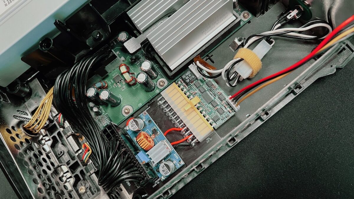
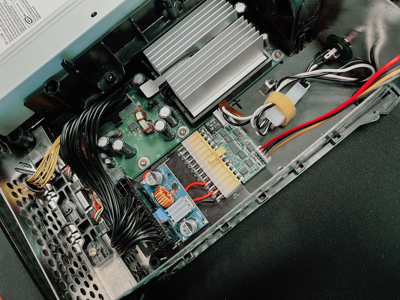
As I mentioned in the previous update, I have bought another Xbox 1.6 to test the levels on the original power supply in both ON and standby modes.
I finally took it apart and did the measurements. The results were surprising, it appeared that I got many things wrong in my prototype design. The fact that it worked at all was a miracle.
As I initially didn’t have a working Xbox power supply on hand I searched for the pinout online. I found one posted on many forums but every thread had comments about errors in the diagram pinout.
I tried to account for every correction that was there but as I’ve learned now, most of them were wrong, the original diagram was very close to the truth. Yes, it looked strange in comparison to other Xbox revisions, but it was the most accurate one:
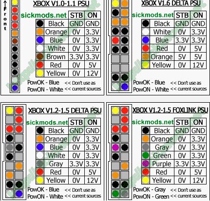
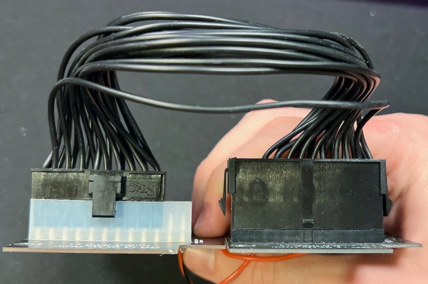
Even though it has the right voltage levels specified, it doesn’t show two important things:
- Orange pins are used for 5V standby and the red one is the main 5V pin. I mixed them up in my original design thinking that standby line would most probably use single pin and not four of them.
- The blue Power_OK signal is actually a 3.3V standby pin as the original Xbox PSU always supplies this voltage even when the console is in standby. As I’ve tested, the console would work even without this pin connected but I’m not sure it is a good idea to do so.
In my previous attempts I was unable to make the Power_ON signal to work (probably because 5V and 5V STB were mixed up) so I had to simply connect it to the ground on the ATX PSU side to make it always on. There were no issues with that until I added DC-DC converter, which was heating up while the console was off.
There were so many discrepancies with my design that I felt lost. I tried to quickly modify the existing prototype but it didn’t work. So I put it aside and spent some time thinking about it. And I’ve made a plan.
I started simple, with just the 5v standby line connected to the Xbox, and checked if it outputs the correct signal on the Power_ON pin of the motherboard when I press the power button on the console.
It worked, so next I connected the Power_ON signal to the PSU with a transistor, so it would ground the Power_ON pin of the PSU when there is a signal on the Xbox motherboard.
Then I connected all the remaining power rails and pressed the button.
Xbox turned on! This was the first time I was able to properly turn on the PSU from the Xbox. I was overjoyed, after so many failed attempts I did not expect it to work.
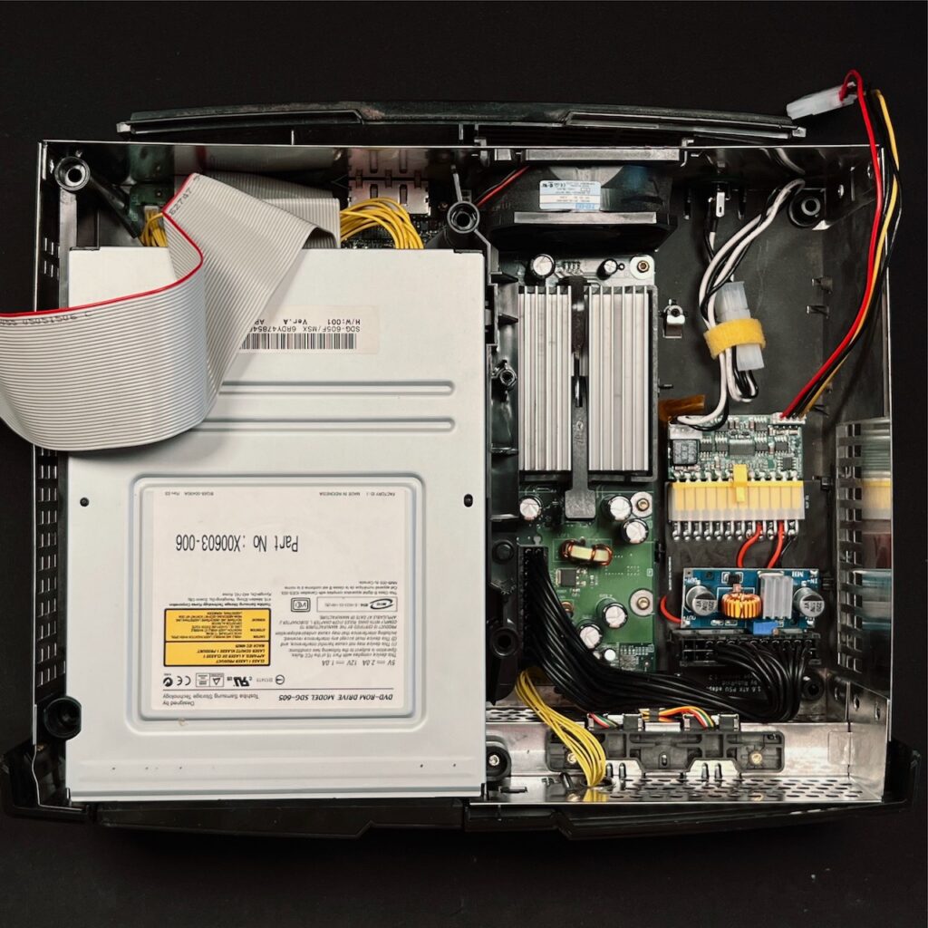
Next I connected the video cable and hooked up the hard drive and watched the console booting.
That was an exciting moment. My adapter wasn’t just simply working as before, it was working properly!
After connecting the DC-DC converter I was happy to see that it wasn’t producing as much heat as before since it wasn’t working when the console was in standby mode.
Few more alterations later the prototype adaptor was outputting all the same levels as the original PSU.
I was so glad that I have designed the board the way it is because it allowed me to do all the alterations easily. It is also very simple to move it in and out of the case and it stays still inside even without a mounting screw. This really helped to make all those alterations fast.
I then played some Halo 2 and found no issues, it worked fine and the DC-DC converter was barely warm even after an hour of gameplay (I’m already at chapter 8).
Finally I took some time to fix the board schematics to reflect all the changes made to the prototype. It wasn’t that hard and my skills got improved greatly since I’ve started the project. I was even able to 3D model the connectors to make them visible on the board 3D view.
Also I decided to change the output connector on the board. The current one is a male connector which I chose because it is very low profile. But the female connector on the cable side that plugs in is much taller. It makes it tricky to put the HDD tray on top so instead I’ll try to use a female connector. Those are a bit taller but the cable side plugs are quite shorter, so this should save a few millimetres and make the installation a bit easier.
This change required rewiring of the board as the connectors are mirrored. This wasn’t that difficult and I liked the result more. I have already designed and ordered this version of the board, so soon I’ll be able to see which approach is better.
I have ordered the new prototype revision and it will most likely take another 2 to 3 weeks until I get it. Hoping that this time it will work as it should without any cut and rewired traces.
So this is it for now. I’m very happy with the current developments and can’t wait for the next batch of prototype boards to arrive.
In case you’re interested in getting the adapter, join the waitlist and I will let you know when it’s ready.
I’m excited to see this project progress. You are, as far as I know, the only person to get this close to designing a power adapter for the v1.6 Xbox. I’ve been on and off looking for one for years. Hope all is well. I look forward to your next update.
Hi, thanks for the reply.
I’m still working on it and waiting for another batch of prototype PCBs at the moment, then I’m going to make a new progress update with some news.
Thanks again!
I have been working on eliminating the IDE cable and going directly from the motherboard to the IDE to SATA adapter on my v1.6 Xbox and deleting the DVD drive. I have the HDMI mod kit as well, but have not installed it yet.
Here are a few pictures of early progress
https://imgur.com/gallery/QeFmwl0
https://imgur.com/gallery/XW3QI6T
Great job! I do have a similar goal of eliminating the IDE cable but I still have a very short one coming from the motherboard to SSD which I mounted to the DVD drive bracket using a 3D-printed part.
I also have an HDMI kit installed in mine which provides a very clean image, good luck getting yours successfully installed too 🙂