After a whole weekend of research with not much sleep, I have finally made some promising progress on the project, yay!
First, let me explain the main issue we’re trying to deal with. OG Xbox revision 1.6 has two 5V lines: 5V standby (I will refer to it as “5V STB” down the line) which is always active, and 5V, which is used when the console is turned on. Sounds simple, right? The problem is that, unlike the PC, when turned on, the Xbox takes most of the current from the 5V STB rail, not the regular 5V rail. This becomes pretty obvious if you simply take a look at the power connector pinout, which has four pins for 5V STB (orange) and just a single pin for 5V (red).

A regular ATX PSU is not designed to provide sufficient current over the 5V STB line, so as soon as Xbox powers on, the PSU will immediately shut down due to the overcurrent protection. To remedy this issue, some kind of source switching should be implemented.
We should supply power from the 5V STB rail of the PSU while the Xbox is in standby mode, and once the power button is pressed, we should switch the source and send current from the 5V line of the PSU into both 5V STB and regular 5V lines of the Xbox.
Now, how can we do this? We can’t simply supply both 5V STB and 5V lines of PSU into the 5V STB line of Xbox as this will damage the PSU. The lines should be separated and switched on the fly when needed.
I tried to make this work in two ways: with a PNP transistor and with a relay.
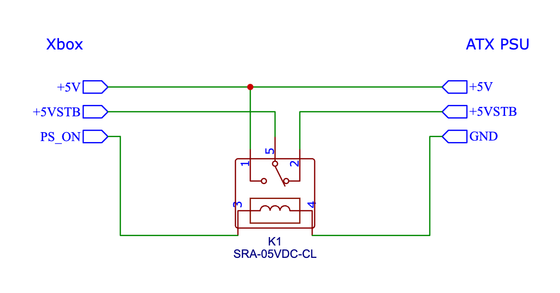
Unfortunately, both of the circuits acted quite unstable, especially the one with a relay: it sometimes worked fine and sometimes the relay was switching back and forth several times a second, which looked pretty scary.
Another issue was that the Power On impulse from Xbox is too short. It’s enough for the relay to switch but not enough for the PSU to start. I needed the pulse to be a little bit longer, so I shorted the PS_ON pin of the PSU to the GND for a second while pressing the Power On button on the Xbox, and it worked fine. Also, this made the relay pretty much useless. Anyway, this was the first time I was ever able to run an Xbox from a regular ATX PSU and I felt quite happy about it. If only there was a better method.
And I think that I have finally found one. At first, I was looking into ways of extending the Power On impulse with something like a 555 timer, but then I realised that by the time the PSU would be ready to provide power over the 5V rail, the Xbox would not wait for it anymore, returning to standby mode. So the switching has to be faster than my PSU is able to turn on.
These experiments have revealed that we can’t rely on the Power On sequence of the console anymore. So why don’t we just bypass it by hijacking the signal from the power button? This way we can send a signal to the PSU, give it enough time to start, and then send a signal to Xbox to power on. We just need to use a simple microcontroller (like an Arduino) that will control the sequence. This should work, right? And it works indeed. Finally!
I used an ESP8266 development board, which I connected in between the Xbox power button and the motherboard, which controls the whole Power On/Power Off cycle. It works exceptionally well and I didn’t have any issues with it so far. It’s a very simple setup and there is still room for improvement. I need to write some more code for the Eject button, adjust the timings, and improve the Power Off sequence which is very basic at the moment.
I’m so glad that I returned to the beginning of the prototyping phase. It gave me more understanding of the problem. Also working with a real ATX PSU (not a PicoPSU as before) allowed me to create an adapter with much higher compatibility. And, finally, it made me understand the reason why such an adapter was never developed before and all previous attempts have unfortunately failed. I hope this is not another one of those.
Now I have ordered more ESP8266 modules, a programmer, and some connectors to build a proper PCB that will go between the Power button cable and the motherboard. I’m going to redesign the prototype board to accommodate the ESP8266 module. I still want to make it more stable by keeping the DC-DC converter for the PicoPSU. Not sure how to fit all this into a pretty small PCB yet but we’ll see. I will post another update once I have more progress on all of this.
In case you’re interested in getting the adapter, join the waitlist and I will let you know when it’s ready.